| GESTRA Steam Systems |
| Issue Date: 11/08 |
| Product Range B |
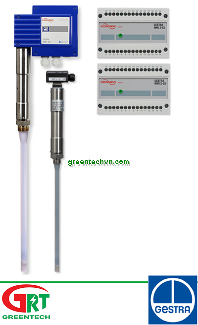
| Compact System for Level Monitoring |
| NRGT 26-1 |
| NRGT 26-1S For Marine Applications |
| NRGT 26-1 |
| NRGT 26-1S |
| Description | |
| The compact system NRGT 26-1 works according to the capacitance measurement principle. The NRGT 26-1 is designed for signalling different levels in conductive and non-conductive liquids: |
| n Water level maintained within the control band defined by two preset limits. |
| The NRGT 26-1 has a level transmitter integrated in the terminal box which produces a standard output signal of 4-20 mA. External switchgear is not required. |
| Function | |
| The principle of capacitance measurement is applied to determine the level. The electrode rod and the vessel wall form a capacitor. If the level of the dielectric located between the two capacitor plates changes, the current which flows through the plates changes proportionally to the level. A dielectric is defined as an insulating substance, which excludes many liquids such as water. In order to receive a useful measuring result the measuring rod, which is completely submerged in the liquid, must be completely insulated. After calibration of the zero point/measuring range (0 % - 100 %) of the control unit, the level can be read off from a remote display unit. The level measuring range can be changed during operation. |
| Design | | |
| NRGT 26-1: | |
| Electrode with screwed connection ¾" BSP, EN ISO 228-1. |
| NRGT 26 -1S: | |
| Flanged design for marine applications DN 50, PN 40, DIN 2635. |
| Technical Data |
| Type approval no. |
| NRGT 26-1: TÜV · WRS · 02-391 |
| NRGT 26-1 S: LR 98/20075 RINA ELE/30298/2 GL 99249-96HH BV 10617/AO BV NKK A-556 DNV A-8394 |
| KR HMB 06190-MS002 |
| Power consumption |
| 5 VA | | | |
| Fuse | | | |
| Thermal fuse T = 102 °C |
| Sensitivity | | |
| Range 1: Water ≥ 0.5 µ S/cm Range 2: Water ≥ 20 µ S/cm Range 3: Fuel oil EL e 2.3 |
| Output | | | |
| 4-20 mA level-proportional. Volt-free, max. load 500 Ω |
| Indicators and adjustors |
| 2 red LEDs for signalling “Level 0 %” or “Level 100 %” within the measuring range, |
| 1 green LED for signalling “Level between 0 % and 100 %” of measuring range. |
| 1 code switch for selecting the measuring range. |
| 2 trimmer potentiometers for small-percentage adjust- ment of the measuring range. |
| 2 terminal lugs for voltage metering. |
| Cable entry | |
| Cable gland with integral cable clamp |
| M 20 (PG 16) (2 x) |
| Protection | | |
| IP 65 to DIN EN 40050 |
| Max. admissible ambient temperature |
| 70 °C | | | |
| Weight | | | |
| NRGT 26-1: Approx. 1.8 kg NRGT 26-1S: Approx. 8.0 kg |
| GESTRA NRGT 26-1 | |
| GESTRA Steam Systems | | | |
| | | |
| Service pressure |
| 32 bar g at 238°C |
| Connection | |
| NRGT 26-1: Screwed ¾", EN ISO 228-1 NRGT 26-1S: Flanged DN 50, PN 40, DIN 2635 |
| Materials | | |
| Body 3.2161 G AlSi8Cu3 |
| Cover tube 1.4301 X5CrNi18-10 |
| Flange 1.0460 P250GH |
| Measuring electrodes 1.4571 CrNiMoTi17-12-2 Electrode insulation PTFE |
| Spacer disc PTFE |
| (design for marine applications) |
| Wiring diagram |
| NRGT 26-1 NRGT 26-1S |
| DC | | | |
| Supply | | | |
| Mains supply | |
| 230 V +/– 10 %, 50/60 Hz |
| 115 V +/– 10 %, 50/60 Hz (optional) 24 V +/– 10 %, 50/60 Hz (optional) |
| 1 2 3 4 5 |
| Thermal | | | |
| 24 V d.c. (optional) |
| Overall length / measuring range |
| See table overleaf |
| 4-20 mA | | | |
| Max. load 500 Ω | |
| PE | | | |
| Earthing screw in housing |
| L N | | | |
| Mains | | | |
| + – | | | |
| 24 V DC | | | |
| fuse | | | |
| Compact System for Level Monitoring |
| NRGT 26-1 NRGT 26-1S |
| For Marine Applications |
| Dimensions | |
| 173 | | | |
| GESTRA Steam Systems | | | |
| 173 | | | |
| GESTRA Steam Systems | | | |
| Important Notes |
| Cable required for wiring: flexible multi-core control cable, min. conductor size 1.5 mm2. |
| GESTRA NRGT 26-1 | | | |
| GESTRA NRGT 26-1S | | | |
| Order and Enquiry Specification |
| GESTRA Level electrode NRGT 26-1, PN 40 |
| Mains supply............................................................... |
| Connection............................................................. |
| Inspection............................................................. |
| Length supplied...................................................... mm |
| Fluid..................................................................... |
| GESTRA Level electrode NRGT 26-1 S, PN 40 for marine applications |
| Mains supply............................................................... |
| Connection............................................................. |
| Inspection............................................................. |
| Length supplied...................................................... mm |
| Fluid..................................................................... |
| The following test certificates can be issued on request, at extra cost: In accordance with DIN EN 10204-2.1, -2.2 and -3.1B. |
| All inspection requirements have to be stated with the order. After supply of the equipment certification cannot be established. For tests and inspection charges please consult us. |
| Key | | | |
| 1 Flange PN 40, DN 50, DIN 2527 Flange PN 40, DN 100, DIN 2527 |
| 2 For the approval of the boiler standpipe with con- necting flange the relevant regulations must be |
| 3 Vent hole | |
| 4 High water (HW) |
| 5 Electrode rod d = 15 mm |
| 6 Protection tube DN 80 |
| ! Reducer DIN 2616, part 2 |
| K - 88.9 x 3.2 - 42.4 x 2.6 W | | | |
| c NRGT 26-1: Measuring range |
| d NRGT 26-1S: Max. length of installation at 238 °C |
| e NRGT 26-1S: Measuring range |
| ATEX (Atmosphère Explosible) |
| ment must not be used in potentially explosive areas. |
| Æ 42 | | | |
| b c | | | |
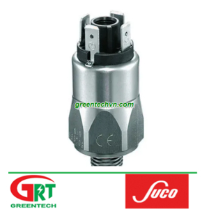
| Fig. 1 NRGT 26-1 |
| ¾" BSP | | |
| DN 50 | | | |
| 4 | | | |
| b = 70 | | | |
| ¾" BSP to EN ISO 228-1 |
| b | c | |
| 373 | 300 | |
| 477 | 400 | |
| 583 | 500 | |
| 688 | 600 | |
| 794 | 700 | |
| 899 | 800 | |
| 1004 | 900 | |
| 1110 | 1000 | |
| 1214 | 1100 | |
| 1319 | 1200 | |
| 1423 | 1300 | |
| 1528 | 1400 | |
| 1636 | 1500 | |
| 2156 | 2000 | |
| 1 | | | |
| 2 | | | |
| 3 | | | |
| 5 | | | |
| 6 | | | |
| 0 | | | |
| Æ 42 | | | |
| | | | |
| d e | | | |
| | | | |
| Fig. 2 NRGT 26-1 S |
| DN 20 | | | |
| b = 70 | | | |
| Flange DN 50, PN 40 |
| Æ 48.5 | | |
| Æ 42.5 | | |
| 1 | | | |
| 2 | | | |
| 4 | | | |
| 5 | | | |
| 0 | | | |
| d | e | |
| 316 | 275 | |
| 420 | 375 | |
| 526 | 475 | |
| 631 | 575 | |
| 737 | 675 | |
| 842 | 775 | |
| 947 | 875 | |
| 1053 | 975 | |
| 1157 | 1075 | |
| 1262 | 1175 | |
| 1366 | 1275 | |
| 1471 | 1375 | |
| 1579 | 1475 | |
| 2099 | 1975 | |
| Supply in accordance with our general terms |
| of business. | |
| Æ 20 |
| Fig. 3 Protection tube for installation of electrode inside the boiler |
| Fig. 4 External measuring pot |
| DN 20 | |