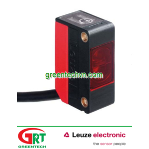
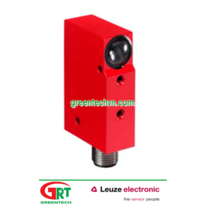
| | Protective function | Application | Leuze electronic products |
|---|


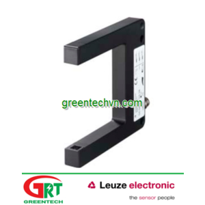
| Machine stop with hand or finger detection | With small operator distance to the danger zone, e.g. with feeding-in work at a press | Safety Light Curtains, Safety Laser Scanners (-E model) |


| Machine stop with detection of person accessing the danger zone | With accessible danger zones and bigger distance to the danger zone | Single Light Beam and Multiple Light Beam Safety Devices, Safety Laser Scanners (‑E model), Safety Switches and Safety Locking Devices (in combination with hard guards) |


| Machine stop with detection of person accessing the danger zone and prevention of the restart with constant presence detection. | Safeguarding danger zone at (accessible) feeding-in areas of machines or guarding driveways on driverless transport systems | Safety Laser Scanners Safety Light Curtains (installed at an angle or horizontal) Light curtains in host/guest configuration |
Step 3: Selecting the required safety type of optoelectronic protective device
The optoelectronic protective device is a component of the safety-related part of the machine control system and a component in the effective chain of a partial safety function consisting of sensor, control unit and actuator. From the risk assessment (graph) in accordance with EN ISO 13849‑1 or EN IEC 62061, the designer determines the safety-related performance required for the risk minimization for this partial safety function (see chapter 2.4 Safety-related parts of control systems or 3.4 Control Reliability, page 29). Regardless of the control system applied, the achieved level of safety-related performance (category, PL, SIL) of the entire safety function is always less than or equal to the lowest value (category, PL, SILCL) of one of its partial systems. Put simply, the chain is therefore as strong as its weakest link.
Optoelectronic protective devices have different safety-related capacities, depending on the detection principle and the internal technical setup. EN IEC 61496 and UL 61496 "Safety of machinery – Electro-sensitive protective equipment" define 3 different types of active optoelectronic protective devices (AOPD), which differ in their effectiveness and frequency of error detection, i.e. their safety-related performance. The following table 4.2.1-1 shows the requirements of this standard. For applications in the USA it must be determined which OSHA / ANSI control reliability requirement is relevant for the respective application case (observe machine-specific and regional specifications!) – see chapter 3 and 3.4, page 29). The corresponding AOPD type must then be selected.
| AOPD type according to IEC / EN / UL 61496 | Functional safety (control reliability) of AOPDs in accordance with IEC / EN / UL 61496 and requirements for the effectiveness and frequency of the error detection |
|---|
| Type 2 | A type 2 AOPD shall have means for a periodic test. A loss of the protective function between the tests is possible if a fault occurs. A fault shall be detected - immediately
- either with the next periodic test
- or with activation of the sensor component
and must result in the switching off of at least one AOPD output. |
| Type 3 (Only defined for Safety Laser Scanners) | Despite a single fault the protective function of a type 3 AOPD is maintained. An accumulation of faults can lead to loss of the safety function. A single fault that causes the loss of the detection capability shall be detected - immediately
- either with activation of the sensor function,
- with switching on/switching off
- with start/restart interlock reset (if available)
- or with an external test (if available)
and shall result in the AOPD outputs being switched off.A single fault that impairs the detection capability shall be detected within the time specified in the relevant part of EN IEC 61496 (5 seconds for Safety Laser Scanners). With the non-detection of the first fault, a second fault may not result in the loss of the protective function. |
| Type 4 | With the occurrence of several faults the protective function of a type 4 AOPD is also maintained. A single fault that causes the loss of the sensor detection capacity shall be detected - within the AOPD response time
and result in the outputs being switched off.A single fault that impairs the response time or the switching off capacity of one of the AOPD outputs shall result in the AOPD outputs being switched off either - within the specified AOPD response time
- with addressing the sensor component,
- with switching on/switching off
- or with the resetting (reset)
|
Table 4.2.1-1: Types and functional safety (control reliability) of electro-sensitive protective equipment in accordance with EN IEC 61496 and UL 61496.
Characteristic parameters, selection aid and risk parameters
The SIL characteristic parameters in accordance with 61508/SILCL, EN IEC 62061 or PL in accordance with EN ISO 13849-1 are specified in the technical data of our safety products.
Note
The SISTEMA PC software of the German Institute for Occupational Safety and Health (IFA) is used for the automatic calculation and evaluation of the functional safety of control systems in accordance with EN ISO 13849‑1. It is an ideal complement to Safexpert and can be downloaded as freeware from www.leuze.com/sistema. It includes a components library with the safety-related parameters of selected Leuze electronic products. For further information, see chapter 2.4.1 .
Help with selecting Leuze electronic protective devices
In the event that no regional or machine-specific specifications, such as European C-standards or OSHA /ANSI standards specify specific types of optoelectronic protective devices, the following selection aid can be used to select the appropriate Leuze electronic safety sensor for the risk minimization. The qualitative method presented in EN ISO 13849-1 is used for determining the required safety level. A risk assessment, e.g. in accordance with EN ISO 12100 must generally be performed beforehand and the previous notes of Chapter 4.2.1 must be observed.
IEC TS 62046 recommends across the board:
| With low risk: | Type 2 AOPD and higher |
| With medium risk: | Type 3 AOPD (Safety Laser Scanners) or type 4 Safety Light Curtains |
| With high risk: | Type 4 AOPD |
Safety notice
The selection of the appropriate type of protective devices for sufficient risk reduction is always the responsibility of the machine constructor or system integrator. No legal claims can be derived from the following selection aid. Regional laws or machine-specific specifications, reasons for product liability or the amount of the material damage can result in the selection of another type of protective device with higher safety-related capacity, contrary to the presented recommendation. If the possibility of serious, irreversible injuries exists, we recommend using an AOPD of at least type 3.
Risk parameters:
| S | Seriousness of injury |
| S1 | Minor (usually reversible) injury |
| S2 | Serious (usually irreversible injury including death) |
| F | Frequency and/or duration of the exposure to the hazard |
| F1 | Seldom to not very frequent and/or exposure to hazard is brief |
| F2 | Frequent to continuous and/or exposure to hazard is long |
| P | Possibility of preventing the hazard or limiting the harm |
| P1 | Possible under certain conditions |
| P2 | Not really possible |
 Fig. 4.2.1-1: Help with selecting point of operation guarding (with hand or finger detection)
 Fig. 4.2.1-2: Help with selecting danger zone guarding
 Fig. 4.2.1-3: Help with selecting access guarding
Step 4: Calculating safety distance
Optoelectronic protective devices can only perform their protective function if they are installed with a sufficient safety distance from the nearest danger point of operation. The safety distance from the protective device to the point of operation must big enough that the dangerous movement will have stopped before a part of the person’s body can reach the point of operation (see also, ANS IB11.19‑2003). After calculating the safety distance it should be checked and ensured that this minimum distance allows an ergonomic operation of the machine for the operator. If this is not the case either an entire stop time of the machine or an AOPD with higher resolution must be selected.
The following overview refers to the calculation formulas of EN ISO 13855/"Safety of machinery – Positioning of protective equipment with respect to the approach speeds of parts of the human body" and the recommendations of IEC TS 62046. If the machine is the subject of a certain specification, such as machine-specific European C-standards and OSHA / ANSI standards, then reference must be made to this. This overview does not, of course, detract from the observation of the installation notes of the operating instructions.
Safety distance calculation in accordance with EN ISO 13855 and IEC TS 62046
The minimum distance of a stop-activating protective device from the nearest danger point of operation on the machine must be calculated with the following formula:
| S = (K x T) + C |
|---|
| S | The minimum safety distance in millimeters from the next point of operation to the detection point (protective field) of the protective device. An "S" of 100 mm must be observed regardless of the calculated value. |
| K | Approach speed in millimeters per second, derived from data of the approach speeds of the body and body parts. Speed (lower limbs): K = 1600 mm/s Speed (upper limbs): K = 2000 mm/s |
| T | Stopping time of the entire system (protective device response time + interface response time + machine stopping time) in seconds (IEC TS 62046 requires at least an additional 10 % on top of the determined stopping time to allow for possible deteriorations). |
| C | An additional distance in millimeters. This additionally added distance is based on the fact that, depending on the resolution of the protective device, a body part can get a certain distance closer to points of operation before it is detected by the protective device. |


